Repeated Shapes / Precision Geometry
Consistent Corner Radii
How to preserve uniform arc geometry, corner curvature, and inner safe zones across variant series without distorting repeated die boundaries.
How to preserve uniform arc geometry, corner curvature, and inner safe zones across variant series without distorting repeated die boundaries.
When a series of labels shares a uniform perimeter, even a fractional shift in corner curvature shatters the perception of a cohesive family. Production cutters follow exact vector nodes; if variable text bounding boxes distort the outer fillet radius during scaling, subsequent sheet cuts drift. Preserving a standardized radius—such as 3.5 mm across all badges—locks the visual rhythm across every container.
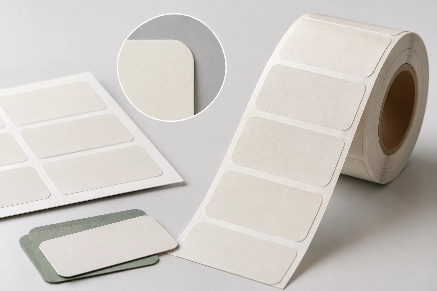
Discover complete layout blueprints for locking corner arcs across custom sheet configurations and varied label dimensions.
Designers frequently assume that duplicating a rounded rectangle ensures geometric fidelity across an entire production batch. When text fields expand from short entries like "Mia" to multi-syllable compounds like "Christopher", inexperienced operators often rescale the entire shape proportionally instead of adapting typographic tracking. The consequence is immediate: corner radii stretch unevenly, creating elliptical corner bends on longer labels while leaving square badges with circular fillets.
Physical cutter blades exacerbate this visual discordance. High-speed plotter heads decelerate into sharp arcs and accelerate out of wide fillets; mismatched corner radii between adjacent cut-paths produce varied drag pressures on release liners. To maintain absolute structural coherence across shelves, every label variant within a run must reference an unyielding geometric template where outer fillets never deform.
Securing identical corner arcs requires decoupling the shape boundary from internal typographic containers. In vector production software, define the external die-cut path once on a master layer, then lock its control points permanently before introducing variable text elements.
By isolating the path profile from content modifications, type scaling engines can reflow, kern, and condense variable names without exerting accidental pull forces on corner anchors. The outer contour stays rigid, stable, and predictable throughout.
During pre-flight verification, compare stacked vector outlines across extreme length variants to confirm that corner curvature outlines overlap with zero micro-gaps. Applying this rigid geometric baseline ensures that finished sheets peel cleanly, look professionally cohesive, and present a uniform brand silhouette across varied container surfaces.